 ar
ar bg
bg hr
hr cs
cs da
da nl
nl fi
fi fr
fr de
de el
el hi
hi it
it ko
ko no
no pl
pl pt
pt ro
ro ru
ru es
es sv
sv tl
tl iw
iw id
id lv
lv lt
lt sr
sr sk
sk sl
sl uk
uk vi
vi et
et hu
hu th
th tr
tr fa
fa ms
ms hy
hy ka
ka ur
ur bn
bn mn
mn ta
ta kk
kk uz
uz ku
ku
load cell wiring diagram
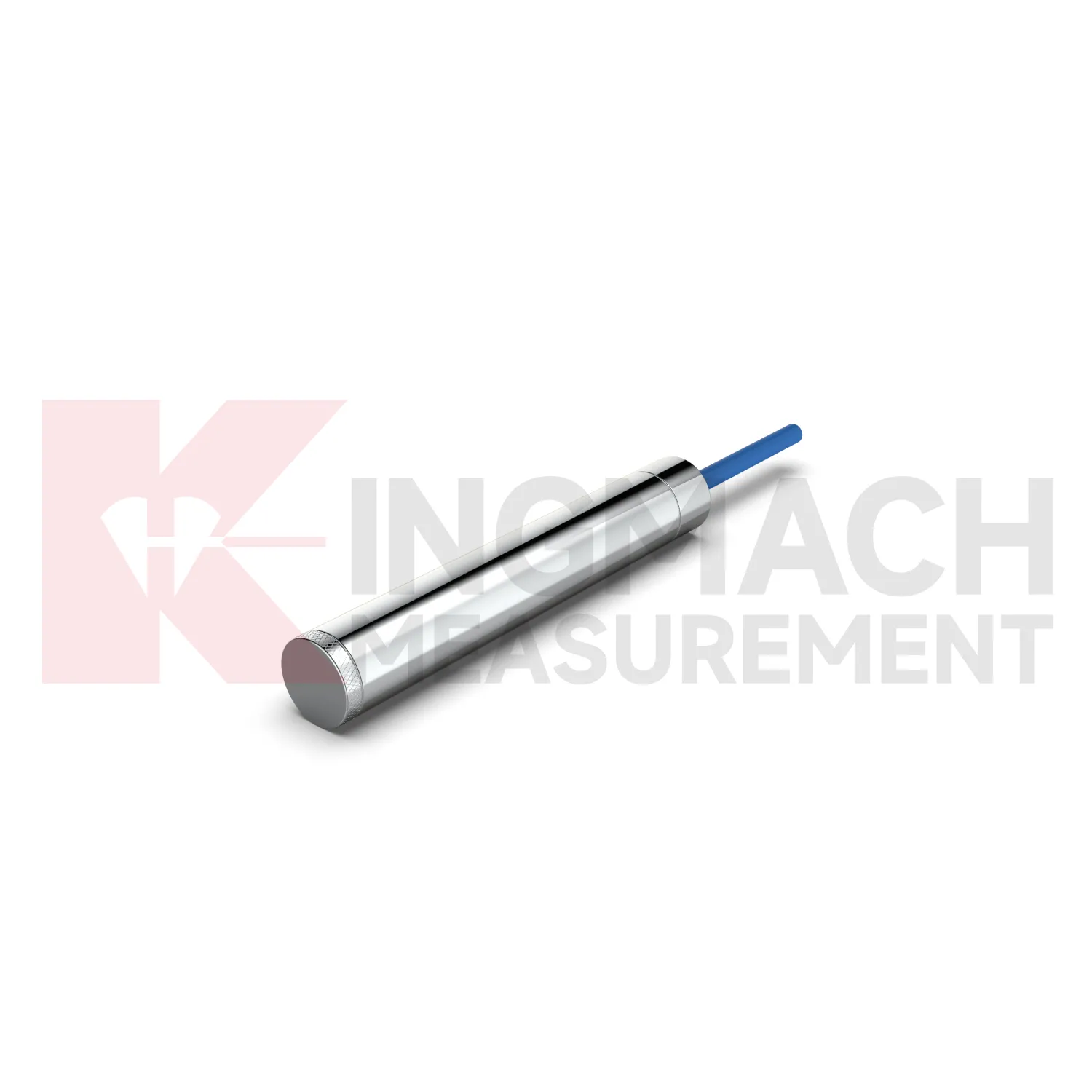
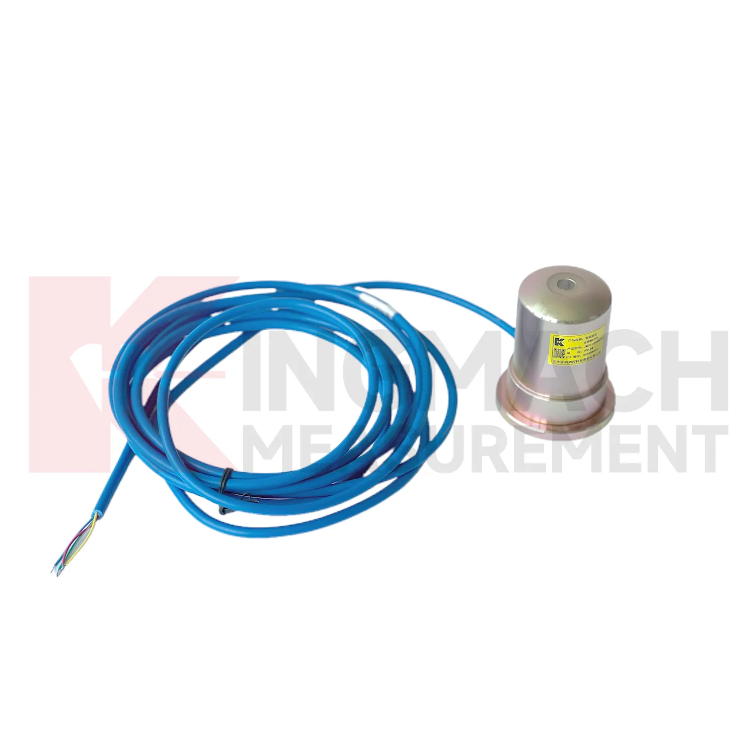
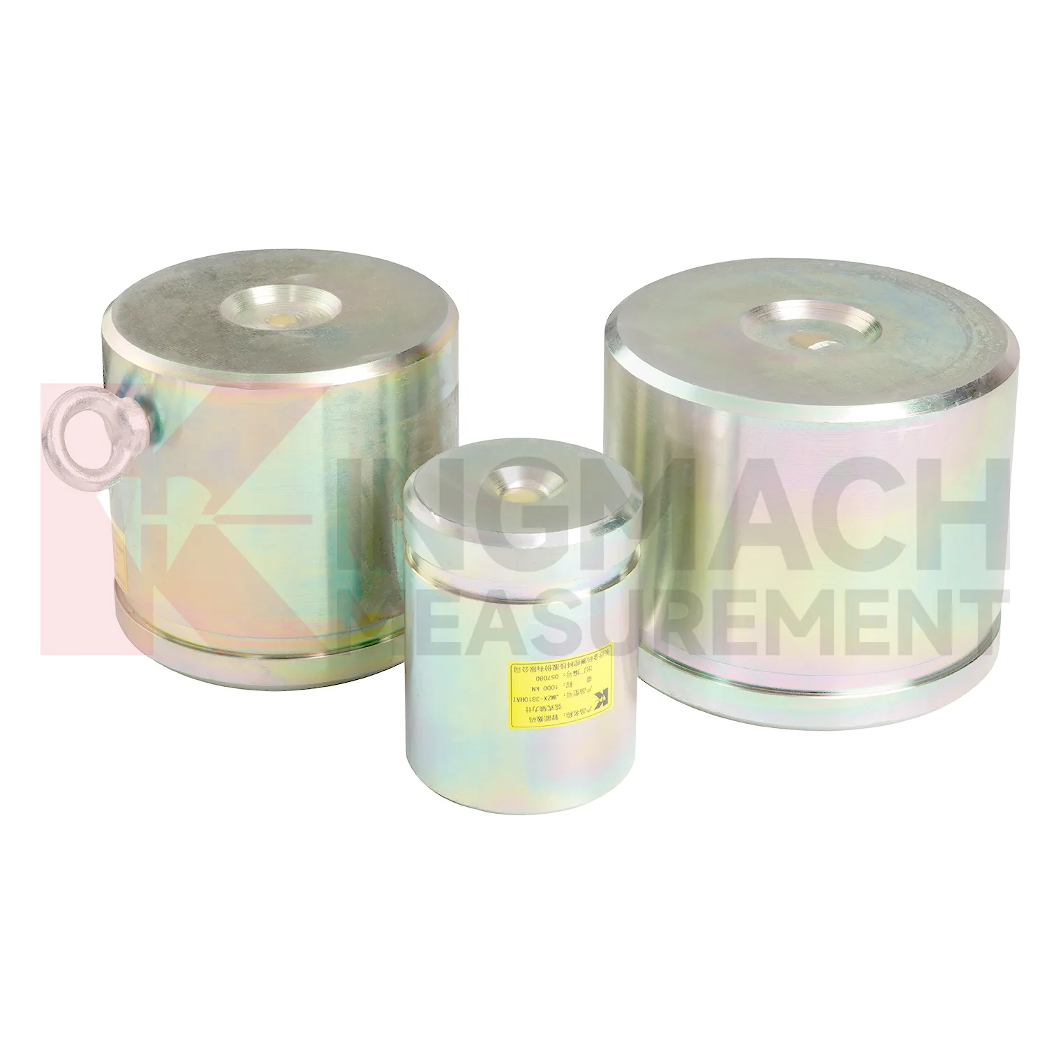
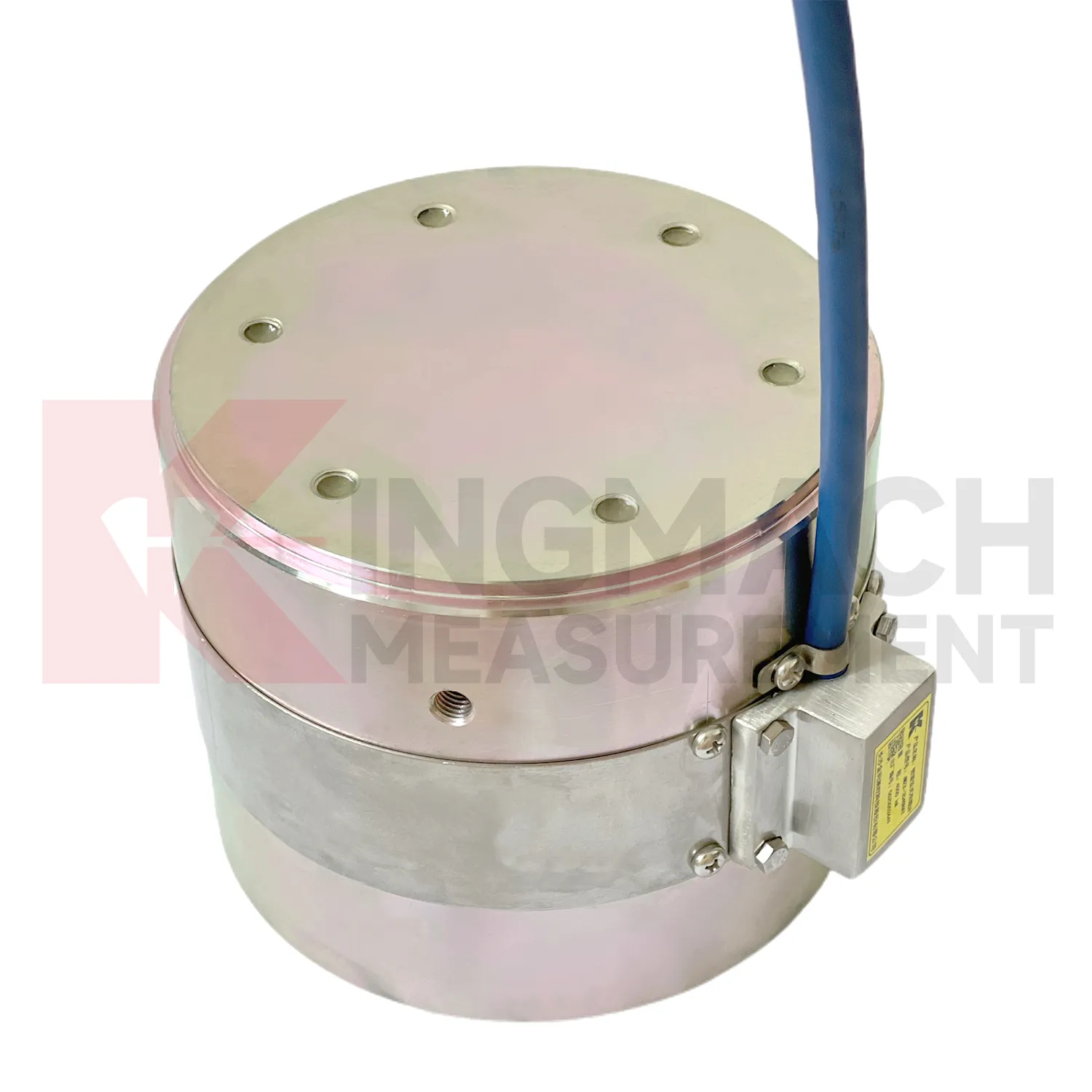
Kingmach load cell wiring diagram descriptions should be read together with the data chain around the sensor. A hollow load cell can cover 500 kN to 8000 kN with a long service design, while the solid load cell line reaches 10000 kN with 0.5%FS precision. The axial force meter adds direct kN display and a 1 MPa waterproof rating for support load monitoring. Smart models include memory for calibration information, zero values, temperature data, and stored measurement records. These are not decorative features. They reduce uncertainty when many sensors are installed across a bridge, tunnel, foundation pit, dam, or rail project. Kingmach supplies readouts and data acquisition equipment, so a single instrument can be used for manual reading during installation and later connected to centralized monitoring if the owner requires it. The better specification path starts with the monitored member, expected load range, access condition, waterproof exposure, temperature swing, cable distance, and reporting method, then selects the model around those constraints. Kingmach's after-sales information also refers to warranty service, anti-static and shockproof packaging, and technical response support. Those points are useful in force monitoring because sensor damage, delivery handling, and setup questions can all affect whether the first readings are trusted.

Application of load cell wiring diagram
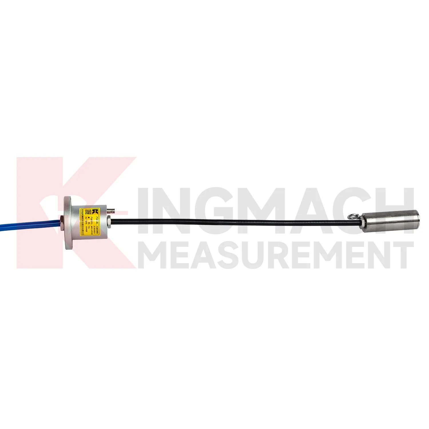
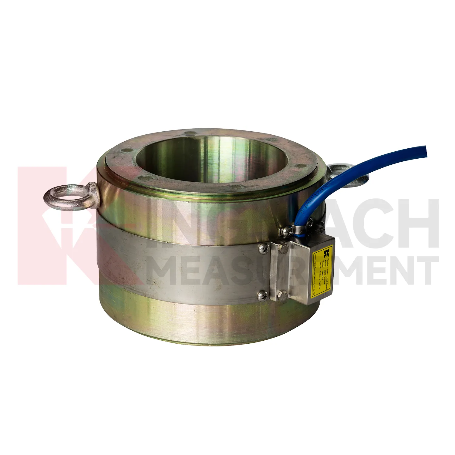
In bridge monitoring, load cell wiring diagram can be used at cable anchor heads, stay cable force points, pier supports, bearing test positions, and pile load test setups. The pain point is simple: a bridge can redistribute force before visible cracks or displacement appear. Hollow load cells such as the JMZX-3XXXHAT cover 500 kN to 8000 kN and are built around an annular multi-string structure with temperature correction and waterproof durability. Solid load cells reach 10000 kN with 0.5%FS precision, which suits high capacity compression points and bearing capacity checks. During construction, readings can confirm prestressing, lock-off behavior, and support load transfer. During operation, the same point can be reviewed after heavy traffic, temperature swings, maintenance work, or extreme weather. Force data becomes more meaningful when compared with displacement transducers, settlement points, tiltmeters, and visual inspection results. For long span bridges, a load trend that drifts slowly can be more important than a single high reading, because it may reveal relaxation, seating loss, or uneven force sharing. Cable exit direction, waterproof joint location, inspection access, and whether the point will be buried or exposed should be decided before installation. Those details are easy to ignore in drawings, but they often decide whether a field crew can verify the reading later without disturbing the structure.
The future of load cell wiring diagram
Future load cell wiring diagram networks will need better alarm logic than fixed thresholds alone. A 5 percent force rise may be routine during concrete curing, serious during anchor relaxation, or irrelevant during a temperature swing. Kingmach products with temperature correction, stored records, digital output, and compatible data acquisition provide the raw structure for richer judgment. The next technical path is multi-parameter comparison: force plus displacement, pressure plus water level, support load plus excavation stage, cable force plus temperature. AI analysis can help rank unusual patterns, but the field team still needs plain evidence: which point changed, how fast, under what condition, and whether nearby sensors agree. Digital twin platforms can make that easier when sensor locations and calibration data are reliable. As monitoring specifications become more demanding, the instruments that win trust will be the ones that keep readings traceable from installation through maintenance, not just during the first acceptance test. Good metadata will matter as much as communication speed.
Care & Maintenance of load cell wiring diagram
For load cell wiring diagram used in pile load testing, care begins before the first load step. Confirm that the selected solid load cell range, often between 1000 kN and 10000 kN on Kingmach listed models, exceeds the planned test load with proper margin. Check the 0.1 kN resolution, 0.5%FS precision, calibration certificate, bearing plate flatness, and centering arrangement. During the test, protect the cable from jack movement and keep the readout position safe from vibration and water. Record zero value, temperature, load stage, hold time, unloading stage, and any pause or adjustment. After the test, inspect the sensor for dents, side load marks, connector damage, and cable jacket cuts. Store the calibration coefficient with the test report, not only with the instrument box. If later readings appear inconsistent, compare them with jack pressure, settlement data, and loading procedure before blaming the sensor. Store the report with the test file.
Kingmach load cell wiring diagram
load cell wiring diagram is useful where the risk is not dramatic movement but slow, uneven load transfer. A bridge cable may relax in small steps, a support jack may settle after locking, a foundation pit strut may gain force overnight, and a dam anchor may respond to water level changes. Kingmach force monitoring products are designed for these long observation periods, with smart chips, temperature correction, waterproof structures, and compatible readouts or acquisition units across several models. The working value comes from repeatable measurement under real site conditions. That includes dust, water, vibration, long cable runs, tight installation space, and crews working around the instrument. A good record helps teams separate normal load fluctuation from a developing problem. It also reduces arguments during handover, because the reading is tied to a named point, a calibrated model, a timestamp, and the same measurement method used throughout the project. The result is a record that can survive handover between contractors and owners.
FAQ
Q: What does load cell wiring diagram do in a foundation pit or tunnel? A: It measures axial force in steel supports, anchor load, or pressure change as excavation and support stages progress. Q: Which Kingmach model fits steel support axial force? A: The JMZX-38XXHAT axial force meter is listed from 200 kN to 3000 kN, with 0.1 kN or 1 kN sensitivity and 0.5%FS accuracy. Q: Is it suitable for wet underground sites? A: The axial force meter lists a 1 MPa waterproof rating, but connector sealing and cable routing still need inspection. Q: Why is direct kN display useful? A: It reduces confusion because teams can read axial force directly instead of converting vibrating wire frequency on site. Q: What should trigger extra checks? A: Excavation step changes, rainfall, dewatering, support adjustment, sudden force jumps, or unstable channels.
Reviews
Daniel Brown
Excellent environmental monitoring sensors. The data is consistent, and the system integrates smoothly with our existing setup.
Joshua Clark
We ordered a full monitoring solution including sensors and data loggers. Everything works seamlessly together. Great supplier!
Latest Inquiries
To protect the privacy of our buyers, only public service email domains like Gmail, Yahoo, and MSN will be displayed. Additionally, only a limited portion of the inquiry content will be shown.
Mia***@gmail.comNetherlands
Dear team, we are interested in your readouts & data loggers compatible with multiple sensors. Do yo...
Harper***@gmail.comIndia
Dear Sir, we are planning to procure a complete monitoring system including strain gauges, tiltmeter...